
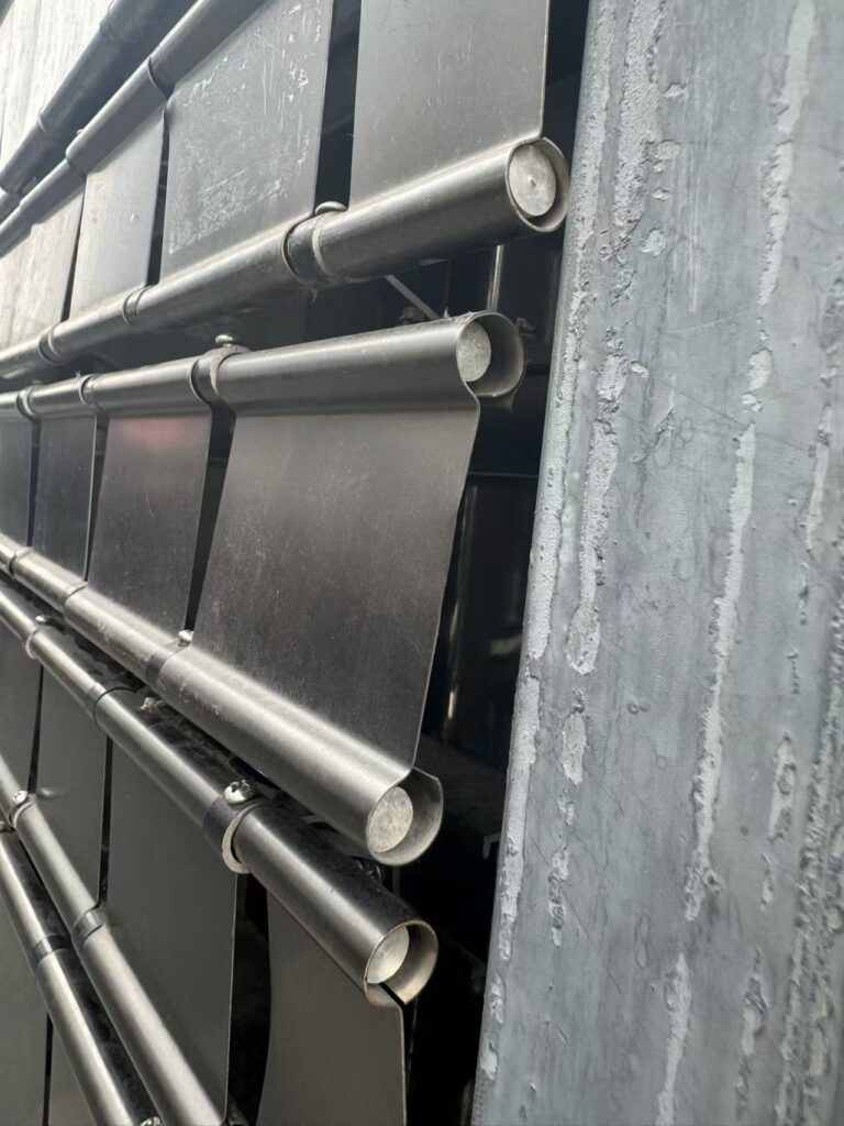
What to Look for in a Kinetic Wall PDF Specification
A practical framework for reviewing design intent, structural interfaces, motion systems, safety, controls, installation and handover documentation before a moving wall enters procurement.
A Useful Specification Explains Decisions, Not Just Products
A reliable kinetic wall specification should allow an architect, engineer, contractor and owner to understand what the installation is expected to do, how it connects to the building, what must be verified, and who is responsible for each interface.
A brochure can introduce finishes, module shapes and visual possibilities. It is not automatically a project specification. A project-ready document needs a defined design basis: installation location, approximate geometry, indoor or outdoor exposure, operating concept, expected viewing conditions and relevant site constraints. It should distinguish confirmed requirements from provisional assumptions. Without that distinction, attractive drawings may create false confidence while important engineering questions remain unanswered.
The document should also be appropriate to the project phase. Early concept material can describe options and coordination needs. A tender package requires measurable scope boundaries and submission requirements. Fabrication information needs verified dimensions, approved materials and coordinated interfaces. Handover records must reflect what was actually installed. Asking one generic PDF to serve every phase often produces gaps or conflicting information.
Identify What Type of PDF You Are Reviewing
Product brochure
Useful for visual direction, typical materials and system families. It should not be treated as final evidence of project performance.
Design specification
Defines outcomes, interfaces, required submissions, testing, quality expectations and responsibilities for the named project.
Shop and record documents
Translate approved intent into coordinated fabrication, installation and as-built information.
A sound package normally contains several linked documents rather than one oversized file. The written specification sets requirements. Drawings communicate geometry and interfaces. Schedules organize components and finishes. Calculations demonstrate engineering assumptions. Method statements explain controlled work. Inspection and test plans identify hold points. Operation and maintenance material supports the owner after completion.
Check the revision number, issue date, project name, author and approval status on every document. A beautifully presented file may still be obsolete. The title block should indicate whether the information is preliminary, for coordination, for approval, for construction or as built. References to other drawings and schedules must match the current register. Revision clouds or a change log help reviewers understand what has changed and whether earlier approvals remain valid.
Start With Purpose, Context and Operating Scenarios
The specification should state why the moving surface is being created. Is it a wind-responsive facade, a motorized lobby feature, a brand display, an interactive installation or a shading element? These descriptions are not interchangeable. Each leads to different performance questions, maintenance expectations and control requirements.
Location information should include orientation, approximate elevation, exposure, neighbouring uses and principal viewing positions. For interiors, note daylight, ambient lighting, acoustic sensitivity, public proximity and operating hours. For exterior work, record the environmental data and design criteria supplied or approved by the project engineer. Local codes, authority requirements and site conditions take precedence over generic supplier examples.
Operating scenarios translate artistic intent into something that can be reviewed. Define normal mode, event mode, resting position, shutdown behaviour and recovery after power interruption. If motion responds to wind, occupancy, scheduled cues or another control system, describe the input and the intended response in plain language. The document does not need to disclose proprietary code, but the project team must understand the observable behaviour.
| Question | Why it matters | Expected evidence |
|---|---|---|
| Who is the audience? | Changes viewing distance, interaction and comfort criteria. | Visitor journey, key viewpoints or design narrative. |
| When does it move? | Defines duty pattern, control logic and neighbour impact. | Operating states and an agreed scene description. |
| What happens when stopped? | The resting surface remains part of the architecture. | Safe position, visual state and restart procedure. |
| Who operates it? | Determines interface complexity and access permissions. | User roles, controls concept and training scope. |
Demand Coordinated Dimensions and Clear Material Definitions
Overall width and height are not enough. The drawing set should show module dimensions, panel spacing, perimeter gaps, projection from the base wall, moving envelope and access zones. Sections are especially important because a front elevation can hide drive depth, support rails, cable routes and conflicts with the ceiling or floor. Critical dimensions should have a stated reference point and tolerance strategy.
Moving components require functional clearance. The documents should separate deliberate shadow gaps from installation tolerances and movement clearance. They should also show how the feature meets adjacent stone, plasterboard, metalwork, glazing, signage or joinery. If site measurement is required before fabrication, identify who measures, which datum is used and when dimensions become frozen.
Material descriptions need more than a colour name. Specify substrate, grade or material family where appropriate, thickness basis, surface texture, gloss or reflectivity intent, coating system, edge treatment and visible fixing expectations. Samples should be reviewed under representative lighting. If natural variation or directional grain is expected, define the acceptable range and orientation rules.
For exterior elements, material selection must respond to the actual exposure, drainage, dissimilar-metal contact, contamination and maintenance environment. For interiors, sharp edges, cleaning agents, fingerprints, fire strategy and public contact may be more relevant. The responsible designers should confirm applicable regulations and testing; a supplier catalogue statement is not a substitute for project-specific approval.
Structural Loads, Supports and Attachment Interfaces
The support concept should show how loads travel from moving elements through frames and fixings into the building. The project structural engineer needs sufficient information to review the substrate and primary structure. Equipment mass, support reactions and dynamic effects should be presented with their assumptions and calculation responsibility. Exterior systems also require project-specific consideration of wind actions and local design criteria.
Do not accept a generic maximum wind figure without context. Ask which standard, location data, pressure zones, safety factors, test configuration and panel geometry support the claim. Wind around corners, openings, podiums and complex building forms can differ from simplified central-field assumptions. The project team may require specialist analysis or testing depending on geometry and risk.
Connections deserve the same attention as visible panels. The drawings should describe anchor type, edge distances, adjustment, corrosion compatibility, locking or retention features and access for inspection. If the backing structure is supplied by another contractor, include a clear interface drawing with load and tolerance information. “Fix to suitable substrate” is not a coordinated detail.
Trace every action
Identify self-weight, operational forces and applicable environmental actions from panel to building.
Verify actual support
Confirm material, capacity, location, embedment and construction tolerance before release.
Plan alignment
Provide controlled adjustment without relying on improvised packing or inaccessible fixings.
Specify Movement in Observable Terms
A statement such as “smooth kinetic motion” is subjective. The project team should describe range, direction, sequence, acceleration, stopping behaviour, repetition and synchronization at a level appropriate to the phase. Reference videos can communicate intent, but they should be accompanied by written acceptance criteria because camera speed, editing and viewpoint can alter perception.
For passive wind-driven panels, review balance, pivot location, bearing concept, panel-to-panel clearance, retention and behaviour under varied airflow. The goal is not continuous identical movement. It is a safe, visually coherent response to natural conditions. The design should also consider calm weather, turbulent zones and conditions that require inspection or temporary restraint.
For motorized systems, the documentation should identify drive architecture, zones, control hierarchy, limit or position strategy, manual isolation and response to faults. The designer should explain whether one failure affects a single module, a group or the entire installation. Accessible replacement and diagnosis can be more valuable than hiding every component behind permanent finishes.
If the wall interacts with visitors, clarify sensor type at a functional level, detection zones, delay, default behaviour and false-trigger strategy. Privacy and network implications should be reviewed by the owner. Many experiences can use anonymous presence or distance sensing; personal identification should never be assumed necessary.
Look for a Risk-Based Safety Strategy
Safety requirements depend on mechanism, speed, force, public proximity, location and local regulation. A specification should not simply list “emergency stop” as a universal solution. It should require a documented risk assessment by qualified parties and explain how hazards will be reduced through geometry, guarding, separation, force limitation, detection, controlled access, operating rules or other appropriate measures.
The safe state must be defined. Consider loss of power, loss of signal, controller fault, obstruction, unexpected movement and maintenance access. Identify whether the installation stops in place, returns to a position or requires manual recovery. The behaviour should be coordinated with relevant building systems and emergency procedures where applicable.
Controls documentation should include a functional description, approved operating modes and responsibility for external interfaces. Network addresses, cybersecurity rules and integration with AV or building management systems may be handled in separate documents, but their boundaries must be visible. The owner should know which functions remain available offline and who can change scenes or settings.
Coordinate Power, Lighting, Access and Building Services
The PDF package should identify electrical supply points, isolation, distribution zones, estimated loads provided for coordination, controller locations and cable routes. Final electrical design and compliance remain subject to the project’s qualified professionals. Cables must be managed so movement, sharp edges and service access do not create damage over time.
Lighting should be studied with the surface geometry and finish. Directional light can produce strong moving shadows; broad light creates quieter tonal change. Reflective panels may redirect glare toward reception desks, retail displays or neighbouring glass. If lighting scenes and motion scenes work together, record the intended sequence and control boundary.
Access drawings should show how technicians reach drives, bearings, connections and replaceable panels after all surrounding work is complete. A hidden access door is not useful if later blocked by millwork or furniture. Note required tools, lifting space and temporary removal sequence. For high installations, coordinate safe access equipment and operating restrictions with the owner.
Check clashes with sprinklers, detectors, speakers, diffusers, signs, doors, curtains and façade drainage. The moving envelope and maintenance zone should be included in coordinated models or drawings. A formal interface workshop before manufacture is a sensible hold point for complex projects.
Samples, Prototypes and Approval Hold Points
Samples should answer defined questions. A finish coupon verifies colour and texture but cannot validate alignment or motion. A single moving module may demonstrate a mechanism, yet a group is needed to judge rhythm and pattern resolution. A full-height bay may be appropriate when perimeter details, access or vertical tolerances are the main risk.
Material sample
Approve finish direction, reflectivity, edge treatment and relationship with adjacent architecture.
Motion prototype
Review movement range, acceleration, noise, stopping and the visual behaviour of coordinated elements.
Integration mockup
Confirm frame, interfaces, tolerances, wiring, service access and finishing before production.
The submittal schedule should state what requires review, who reviews it and whether work may proceed before approval. Typical items include drawings, calculations, material data, samples, mockups, control descriptions, method statements, inspection plans and handover documents. Approval should not transfer the supplier’s technical responsibility or remove the contractor’s obligation to coordinate.
Record prototype conditions and decisions with photographs, video, measurements and written comments. If mass, geometry or motion changes, check the effect on structure, drives, clearances and controls. A clear approval record prevents later disagreements based on different memories of the sample.
Fabrication, Packaging and Site Logistics
Fabrication information should include traceable materials, controlled dimensions, inspection points and handling rules for finished surfaces. The specification may require a quality plan appropriate to the project. This can identify incoming material checks, in-process inspections, assembly trials, functional testing and records required before shipment.
Module size should respond to factory capability and site access. Review vehicle unloading, doorway and elevator dimensions, turning space, lifting equipment, temporary storage and movement through finished interiors. Packaging must protect edges, coatings and precision components while allowing inspectors to identify contents without unnecessary handling.
International delivery adds documentation, customs, storage and responsibility questions. Identify who receives the shipment, reports damage and preserves components until installation. Environmental limits for storage should be stated where relevant. A sequence-based packing list can reduce site handling and help crews install modules in the planned order.
Site readiness should be verified before mobilization. The support structure, power, access route, working area and surrounding finishes need defined acceptance checks. If dimensions are outside tolerance, the team should follow an agreed resolution process rather than forcing precision assemblies into unsuitable conditions.
Require a Controlled Path From Delivery to Acceptance
The installation method statement should address sequence, temporary support, lifting, alignment, fixing, electrical connection, protection and safe working zones. It must suit the actual site and be reviewed by the responsible parties. Generic diagrams are useful only when supplemented with project dimensions and interfaces.
Inspection and test plans should identify hold points before work becomes concealed. Substrate acceptance, anchor installation, frame alignment, cable checks, module movement and perimeter finishing may each require records. The extent depends on project risk and contractual requirements, but acceptance should not rely only on a final visual walk-through.
Commissioning should verify the complete installed behaviour: alignment, clearances, motion scenes, controls, stops, recovery after interruption, lighting coordination and any external triggers. Testing should take place under representative conditions. Record approved settings and software versions so the operating state can be restored later.
Define the defect and closeout process. Open items need an owner, target action and evidence of completion. The final acceptance record should distinguish cosmetic observations from functional or safety issues. Occupancy or a launch event should not silently become the first full system test.
Maintenance Information Must Match the Installed System
The operation and maintenance package should be written for two audiences. Everyday operators need concise instructions for approved scenes, start-up, shutdown and what to do when something looks unusual. Trained technicians need drawings, component references, access procedures, diagnostic information, inspection guidance and safe isolation requirements.
As-built drawings should show actual module locations, access points, control equipment and routes. Include accepted settings, configuration backups and a record of approved changes. Spare parts recommendations should identify purpose, quantity basis, storage needs and any finish-matching considerations. Vague advice to “check regularly” is not a maintenance plan.
Inspection frequency depends on operating hours, mechanism, environmental exposure and site conditions. The responsible supplier and project professionals should establish an appropriate plan. Records can track observations, replacements and recurring issues. Accessible, modular components generally make responsible maintenance easier and reduce disruption to surrounding spaces.
Training should happen with the installed equipment and named owner representatives. Confirm who may operate, reset, isolate or modify the system. Provide contact and escalation routes. If future scene updates are permitted, document the review and testing process because a software change can alter motion demand and visitor comfort.
Use a Responsibility Matrix to Compare Proposals
Two quotations can show similar totals while covering very different scopes. Create a matrix for design development, engineering, backing structure, frames, moving elements, finishes, drives, sensors, controls, power distribution, external integration, packaging, freight, installation, access equipment, testing, training and documentation. Mark each item as included, excluded, provisional or by others.
Also compare assumptions. One supplier may price from verified dimensions; another may assume a standard module count. One may include a coordinated mockup; another only a finish sample. Clarify warranties, response routes and the location from which support is provided without treating warranty length alone as proof of quality.
| Submission | Review focus | Common warning sign |
|---|---|---|
| Design narrative | Purpose, modes and measurable outcome | Only marketing language and renderings |
| Technical drawings | Dimensions, interfaces, access and revision | No sections or coordinated reference points |
| Engineering evidence | Named assumptions, standards and responsibility | Generic performance figure without context |
| Controls description | Behaviour, faults, roles and integration boundary | Component brands listed without logic |
| Handover scope | As-builts, training, settings and maintenance | Documentation deferred without contents |
Twenty Questions Before You Approve the Package
A complete answer does not mean every detail is fixed at concept stage. It means the team knows which information is confirmed, which remains to be developed, who owns it and when it must be approved. That clarity is the real value of a professional specification.
Questions Architects and Buyers Commonly Ask
Can a supplier brochure be used as the tender specification?
It can provide reference information, but a tender document should add project outcomes, scope boundaries, submissions, coordination duties, testing and acceptance requirements. Generic product content should be checked against local codes and site conditions.
Should exact performance values appear in an early concept document?
Only when they are supported and appropriate to the phase. Otherwise state assumptions and required verification. False precision can be more damaging than a clearly identified open item.
What drawings are essential?
At minimum, coordinated plans, elevations and sections should communicate geometry, movement, support, access and interfaces. Complex projects may require details, schedules, control diagrams, calculations and coordinated models.
How can competing proposals be compared fairly?
Issue the same design basis and responsibility matrix to every bidder. Compare inclusions, assumptions, prototype scope, documentation and service responsibilities as well as price.
Does a PDF replace engineering review?
No. It organizes information and requirements. Qualified professionals must assess the specific structure, environment, safety obligations and local regulations for the project.
Need a Project-Specific Specification Review?
Send your approximate dimensions, application, reference images, project location and required movement concept. We can help organize the technical questions for a custom kinetic wall proposal.