
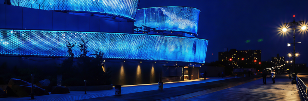
Kinetic Wall Panels: Materials, Sizes, Mounting & Specifications
How to select moving panel materials, establish practical module geometry, coordinate supports and write a project brief that manufacturers, architects and contractors can evaluate clearly.
Choose the Panel as Part of a Complete Moving Assembly
The visible tile is only one layer of a kinetic installation. A successful specification connects panel material and dimensions with bearings, pivots, support frames, clearances, environmental exposure, maintenance access and the desired visual response.
Selection should begin with the architectural effect and site conditions rather than a standard catalogue size. A large element can create broad, legible waves from a distant viewpoint, while a field of smaller elements produces finer visual resolution. Lightweight reflective pieces respond differently from heavier opaque plates. Indoors, the team may prioritize acoustic comfort, controlled lighting and visitor proximity. Outdoors, wind actions, drainage, corrosion, fatigue and building interfaces become central engineering questions.
A professional proposal should separate confirmed project requirements from assumptions. Overall dimensions, location, viewing distance, surface finish, movement type and operating expectations form the design basis. From there, qualified project parties can develop the panel, mechanism and support system together. No generic article or brochure replaces site-specific engineering and local compliance review.
Compare Materials by Performance and Visual Behaviour
Aluminium and stainless steel
Useful where low mass, crisp fabrication and durable finishes are important. Grade, thickness, surface treatment, edge detail and dissimilar-metal contact require project review.
Engineered lightweight panels
Can provide stiffness at lower weight and support printed or coated surfaces. Core, edge sealing, fire strategy and exterior suitability must be clearly defined.
Translucent or decorative media
May create layered lighting effects for interiors and controlled displays. Scratch resistance, UV exposure, cleaning and replacement consistency deserve early testing.
Material descriptions need more than a colour name. A useful schedule identifies the substrate or material family, nominal thickness basis, finish process, gloss or reflectivity intent, edge treatment, grain direction where relevant and acceptable sample variation. The same silver appearance can behave very differently when polished, brushed, bead-blasted, anodized, coated or printed.
Weight affects far more than shipping. It influences bearing demand, acceleration, support reactions, manual handling and the ease of replacement. Stiffness matters because a thin panel that visibly deforms may alter clearances or create inconsistent reflections. For wind-responsive systems, balance and inertia affect how movement begins, how quickly it changes and how it settles. These properties should be evaluated in a representative prototype.
Exterior material selection must reflect the real atmosphere, orientation, pollutants, salt exposure, moisture paths and cleaning plan. Drainage should prevent water from remaining in joints or behind trim. Where different metals meet, the detail should address compatibility and isolation. Interior projects may face different risks: frequent public contact, fingerprints, cleaning chemicals, sharp edges, acoustic sensitivity and heat from integrated lighting.
Use Compact Image Pairs to Compare Surface Effects
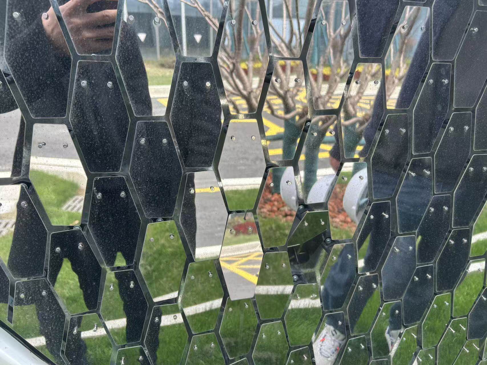

Images are most useful when they answer a design question. Compare the apparent joint width, highlight behaviour, repetition, edge definition and how the field looks from several distances. A dramatic close-up may conceal the fact that the pattern loses clarity from the entrance. Conversely, a subtle finish may become richer when hundreds of panels respond together under directional light.
Reference photography should never be interpreted as an exact colour or performance promise. Camera exposure, post-processing, screen calibration and site lighting all influence appearance. Use images to establish direction, then approve physical samples and a representative moving mockup under project conditions.
Determine Size From Viewing Distance, Pattern and Mechanics
There is no universal ideal module. Panel width and height should be considered with the overall wall area, desired visual resolution, viewing distance and movement type. Smaller modules can create detailed ripples and gradual transitions but increase the number of pivots, bearings, attachment points and maintenance items. Larger modules reduce repetition and create stronger individual reflections, yet may need greater depth, clearance and structural capacity.
Aspect ratio affects both appearance and balance. Squares create a regular field, vertical rectangles emphasize height and horizontal elements can produce banded movement. Circular, faceted or custom shapes introduce distinctive shadows but may complicate nesting, perimeter conditions and replacement. The project team should review the whole elevation, not only an isolated tile.
| Decision | Design effect | Technical coordination |
|---|---|---|
| Module scale | Controls pattern resolution and reading distance. | Changes element count, weight, fixing quantity and access. |
| Panel spacing | Defines transparency, shadow lines and visual rhythm. | Must include fabrication tolerance and movement clearance. |
| Projection and depth | Creates stronger highlights and layered shadows. | Affects structure, adjacent finishes and service zone. |
| Perimeter treatment | Determines whether the field looks framed or continuous. | Requires coordinated tolerances at floors, ceilings and corners. |
Movement clearance is functional and should not be reduced simply to achieve a narrower joint in a rendering. The required gap depends on geometry, range, tolerance, thermal movement, installation accuracy and potential deformation. Drawings should distinguish visible design gaps from hidden mechanical clearances. Corners, reveals and irregular boundaries need special attention because standard modules may not divide evenly into the available dimensions.
A good layout study tests several module counts against the verified opening. It should show how partial modules, trim pieces or margins are handled. If the building opening changes after fabrication, the adjustment strategy must not transfer excessive tolerance into panel spacing or compromise the moving envelope.
Match the Panel to Passive or Motorized Motion
Passive systems use environmental energy, most commonly airflow, to create naturally varying motion. The panel, pivot, balance and bearing act together. A lighter element may respond to gentler airflow, but the complete system still needs safe retention and project-specific assessment of wind actions. Movement will vary with real conditions; it should not be presented as a perfectly repeatable programmed animation.
Motorized installations provide controlled scenes, timing and synchronization. Panel mass and geometry influence drive selection, acceleration and energy demand. The specification should describe the observable motion, approved operating modes, stopping behaviour and response to faults. A component brand alone does not explain how the complete wall behaves.
Interactive panels add a sensing and control layer. The team should define detection zones, response delay, false-trigger behaviour, privacy requirements and what happens when the external input is unavailable. In many spaces, simple anonymous presence detection is more appropriate than complex tracking. The technology should support the visitor experience rather than distract from it.
Natural variation
Evaluate balance, pivot position, airflow, calm conditions, retention and the visual effect of non-uniform movement.
Repeatable scenes
Define range, speed, acceleration, synchronization, safe states, operator roles and recovery after interruption.
Responsive behaviour
Document sensor zones, default mode, public proximity, network boundary and ownership of future content changes.
Coordinate Supports, Frames and Building Attachments
The support system transfers panel weight, operating forces and applicable environmental actions into the building. Drawings should trace this load path through pivots or drives, secondary rails, main frames, anchors and the verified substrate. The structural engineer needs defined reactions and assumptions suitable for the project phase.
Wall construction shown in an architectural model may not be adequate for direct attachment. Decorative plasterboard, cladding or joinery often conceals the real structural support. If another contractor provides backing steel or embedded plates, issue an interface drawing that states location, load, tolerance, finish and inspection responsibility. Wording such as “fix to suitable wall” is not enough for procurement or construction.
Adjustment is essential. Frames may need controlled movement in multiple directions so the visible panel field can remain aligned even when the building substrate is within normal construction tolerance. Adjustment should be lockable, accessible and documented; crews should not rely on improvised packing. Perimeter trim should conceal necessary tolerance without blocking movement or future service.
Verify substrate
Confirm actual material, capacity, location and tolerance before manufacturing the final support interface.
Install and align frame
Establish datums, check plane and spacing, record fixings and complete concealed inspections.
Fit and test modules
Install in a controlled sequence, verify clearances and operate representative zones before finishing edges.
Freestanding, suspended and ceiling-integrated installations require their own structural and access strategies. Suspension points should not be assumed available merely because a ceiling grid exists. Floor-supported frames may need coordination with slabs, waterproofing or underfloor services. Every concept must identify which construction package provides the primary support.
Review Edges, Retention, Fatigue and Public Proximity
Moving installations require a project-specific risk assessment. Panel edges, gaps, speed, force, reach zones and public behaviour all influence the safety strategy. Risk reduction may combine geometry, separation, guarding, force limitation, detection, controlled access and operating rules. Requirements must align with the local project team and applicable regulation.
Retention needs attention even where normal movement is gentle. The design should consider foreseeable loosening, component wear and conditions outside normal operation. Fasteners, pins and bearings should be selected and secured for their role, with inspection access where required. Exterior systems also need appropriate response to extreme conditions and site procedures defined by qualified parties.
Durability is not a single material claim. Repeated motion can affect holes, edges, coatings, connections and cables. The prototype should reproduce representative interfaces and movement. Testing should be connected to declared assumptions; an unrelated laboratory result or a sample with different geometry may not support the final design.
Acoustic comfort matters for interiors. Panel contact, bearing noise, drive sound and vibration transferred into architectural surfaces can be more noticeable in a hotel or gallery than in a workshop. Review the sample at the expected visitor distance and against the venue’s normal background environment.
Test the Moving Surface Under Project Lighting
Panel motion becomes visible through changing reflection, shadow, overlap and transparency. Lighting therefore belongs in the design study. Broad sources reveal gradual form, while directional sources create sharper highlights and animated shadows. The position of downlights, glazing and digital displays can either strengthen the effect or produce unwanted glare.
Evaluate samples under the intended colour temperature and approximate brightness. Highly polished materials may reflect visitors and nearby luminaires. Matte or brushed finishes create quieter transitions and can be easier to control in visually busy spaces. Translucent elements require coordination of diffusion, hotspots, cable shadows and access to light sources.
If motion and lighting share programmed scenes, document the relationship: brightness, fade, motion speed, transition and default state. Staff should have a simple approved interface. A large library of effects is less useful than a small set of scenes that suit everyday operation, events and resting periods.
Plan Tolerances, Modules and Site Sequence
Modular construction can improve quality and site efficiency, but module boundaries must support the visual pattern and access strategy. Frames should fit delivery routes, elevators, doorways and lifting constraints. Packaging needs to protect finished faces and precision mechanisms while allowing installers to identify parts in sequence.
Before production, verify the opening, support conditions and adjacent finishes. Agree which dimensions are fixed and which remain adjustable. A coordinated drawing register prevents fabrication from using an older architectural background. Late changes in ceiling height, wall build-up or signage can affect clearances even if the overall elevation appears unchanged.
The installation method should describe unloading, storage, lifting, frame alignment, fixing, panel placement, electrical connection where relevant, protection and inspection hold points. Concealed anchors and cable routes may need records before closure. Trial operation of a representative zone can reveal alignment or noise issues before the entire field is installed.
Commissioning should confirm clearances, motion, controls, stops, restart behaviour, lighting coordination and visible finishing under normal site conditions. Accepted settings and software versions should be recorded. Unresolved items need owners and closure evidence rather than disappearing into a general completion statement.
Information to Include in a Request for Proposal
A complete brief does not require the client to solve the engineering. It gives designers and manufacturers enough context to develop a relevant proposal and state their assumptions. This makes quotations easier to compare and reveals gaps before they become site changes.
Compare Proposals on Scope, Evidence and Long-Term Use
A quotation for a moving wall should be read as a scope document, not only as a total price. One proposal may include design development, engineering submissions, samples, control programming, packaging, installation supervision and commissioning, while another may cover only fabricated panels and frames. Create a responsibility matrix so each bidder responds to the same list of deliverables and interfaces.
Ask suppliers to identify the design assumptions behind their module count, materials, support concept and operating system. Confirm whether dimensions are based on verified site information or an approximate architectural opening. Provisional quantities and excluded work should be visible. If alternatives are offered, the supplier should explain how they change appearance, movement, access, durability and coordination rather than presenting them only as cost reductions.
| Comparison item | What to request | Why it matters |
|---|---|---|
| Panel and finish | Material basis, edge detail, sample and acceptable variation | Prevents visually different products being compared as equivalent. |
| Support and fixing | Frame scope, reactions, adjustment and substrate assumptions | Reveals work that may otherwise move into the main contractor’s budget. |
| Motion and controls | Operating modes, zones, interface boundaries and fault behaviour | Shows whether the proposed experience and operational needs are included. |
| Delivery and installation | Packaging, freight, access equipment, labour and site responsibilities | Clarifies the real route from factory completion to an installed wall. |
| Closeout | Testing, training, as-built records, spares and support route | Protects the owner’s ability to operate and maintain the feature. |
Programme should be reviewed in the same structured way. Separate time for design coordination, sample approval, engineering review, verified measurement, production, transport, installation and commissioning. A short fabrication promise may not include the decisions that must occur before fabrication can responsibly begin. Identify approval deadlines and the consequences of late changes.
Finally, consider ownership after opening. The lowest initial cost may not provide accessible parts, useful records or a practical service method. A responsible comparison considers maintainability, replacement strategy and the availability of technical support alongside visual quality and capital cost.
Design for Inspection, Cleaning and Replacement
Access should be planned while the wall is being designed. Technicians may need to inspect bearings, pivots, fasteners, drives, sensors, wiring and support connections. Removable panels or access doors must remain reachable after furniture, signage and decorative trim are installed. High-level systems require a safe access method coordinated with the owner.
Cleaning guidance should reflect the actual finish. Abrasive products may alter sheen, while aggressive chemicals can affect coatings or plastic surfaces. The owner needs simple instructions that identify permitted materials, safe isolation and whether panels can be cleaned in place. Exterior contamination and drainage may change inspection needs.
Replacement strategy is part of visual quality. Keep records of material batch, finish process, geometry and orientation. A spare panel stored badly may not match when needed. Modular parts should be identifiable, but interchangeability must not be assumed if balancing or calibration is required.
Handover should include as-built drawings, approved settings, component references, inspection guidance, training and contact routes. Everyday operators need different information from technical personnel. Documentation must match the installed version, not an early proposal.
Common Questions About Moving Wall Panels
Is a smaller panel always more responsive?
No. Responsiveness depends on mass, balance, bearing friction, geometry and the available driving force. Small elements increase pattern resolution but also increase component count.
Can one material be used for every environment?
No. Exposure, loads, fire strategy, cleaning, public contact and finish expectations differ. The complete build-up needs project-specific review.
How should panel size be specified?
Give the desired visual effect, overall area, viewing distance and preliminary module range. Final geometry should be coordinated with mechanics, supports and verified dimensions.
Are hidden fixings always preferable?
They can improve appearance, but inspection and replacement access still matter. A discreet accessible fixing can be more responsible than a completely concealed connection.
How to Record the Final Design Basis
Before releasing production, consolidate the approved decisions into one short design-basis record. List the verified opening, module arrangement, finish sample reference, movement concept, support interface, power and control boundaries, approved mockup, access method and outstanding site dependencies. Link each item to the current drawing or submission rather than relying on meeting notes scattered across different teams.
This record helps the architect, manufacturer and contractor work from the same assumptions. If a later request changes panel size, finish weight, movement range or perimeter geometry, the team can trace which calculations, drawings, samples and programme activities need review. Change control is especially important for moving assemblies because a visual revision can influence balance, clearances, structure and controls at the same time.
At handover, update the design basis to reflect the installed condition and connect it with as-built information. The owner then has a concise explanation of what was delivered, how it should operate and where to find detailed maintenance records. This continuity from concept to operation reduces uncertainty and supports responsible future modifications.
What should a prototype demonstrate?
It should answer named questions about finish, movement, sound, clearances, alignment or integration. The sample scale must match the decision being made.
Discuss Your Panel Layout and Specification
Send the project location, approximate dimensions, reference images and desired movement. We can help organize the information needed for a custom proposal.
Request a Project Review on WhatsAppDiscuss Your Kinetic Facade Project
Share your dimensions, application, material requirements and project schedule with our engineering team.
Request a Project Consultation